Kitfox Aircraft Stick and Rudder Stein Air Grove Aircraft TCW Technologies Dynon Avionics AeroLED MGL Avionics Leading Edge Airfoils Desser EarthX Batteries Garmin G3X Touch
Page 13 of 47 FirstFirst ... 39101112131415161723 ... LastLast
Results 121 to 130 of 466

Thread: The Barn Find Build

  1. #121
    Senior Member Eric Page's Avatar
    Join Date
    Jun 2020
    Location
    Toledo, WA
    Posts
    872

    Default Re: The Barn Find Build

    Quote Originally Posted by alexM View Post
    I tend to agree with this. I only have my own doors to compare with, and I need to revisit them because I see the lexan material sitting smooth one day and serious puckers on other days - and that's just sitting on the shelf in my hangar. My doors have what looks like black 3M VHB which would cover all those "lightening holes" you have now.

    I'm real sure VHB would be the wrong material to use since it would defeat the oversize holes in the lexan to allow for expansion/contraction, but some kind of gasket material still seems in order.
    I'm so glad you posted this. It made me go back and look at the bubble door installation instructions (which I had only briefly skimmed), and I found that it calls for using 3M 06382 Acrylic Plus attachment tape. That will cover virtually all of the excess holes, so I really only need to get a few on the back side and on the top and bottom of a couple tubes welded closed. Thank you!!

    Quote Originally Posted by alexM View Post
    As for your control column piece I know the spot you're referring to all too well. Mine is just barely doable as is and it is obvious that a hole drilled even 1/16" off could result in the condition you're experiencing.
    Yeah, I've wracked my brain and I can't think of another way to get a bolt and nut on there, so I'm going to try the rivets. I ordered a couple of different grip lengths, so I'll just use whatever seems to fit the best.
    Eric Page
    Building: Kitfox 5 Safari | Rotax 912iS | Dynon HDX
    Member: EAA Lifetime, AOPA, ALPA
    ATP: AMEL | Comm: ASEL, Glider | ATCS: CTO
    Map of Landings

  2. #122
    Senior Member Eric Page's Avatar
    Join Date
    Jun 2020
    Location
    Toledo, WA
    Posts
    872

    Default Re: The Barn Find Build

    I discovered today that the little red bottle I had pictured in my head, which I thought was Loctite, was actually lubricant. Probably not the best thing to secure bearings in their sockets, so I ordered a couple bottles of different formulas from Amazon. They'll be here Monday, then I can get back to the control column assembly.

    With that on hold, I moved to fabricating a new elevator push-pull tube (the original was badly dented). The raw tube comes from Kitfox at 121". The manual calls for a length of 115-3/4" for a taildragger, so I set up my miter saw, made the cut, then used a file to lightly deburr the ends of the tube, inside and out.

    Next I fixtured the bushing adapters with a 1/4" bolt and nut so that I could chuck them in the drill press to sand their OD to fit the ID of the tube. That went smoothly (no pun intended) and I got a nice fit at both ends, with no wiggle.

    Next step is to drill the tube and adapters for rivets. It was at about this point that I realized that what I thought were male rod end bearings were actually female, and the threads are separate parts of the assembly that are also riveted to the bushing adapters. My originals are Scotch-Welded to the old adapters and I neglected to order new ones, so... Aircraft Spruce to the rescue! Those will be here Christmas Eve.

    Moving on... I'm sure there are lots of ways to drill the center of a tube, but here's what I did. First I cut a small piece of wood (very dense old-growth Douglas Fir, in this case; left over from building my house) to just over 1" in width, then sanded it to exactly 1" (to match the tube's OD).

    IMG_0881.jpg IMG_0882.jpg

    Then I sprayed the top of it with primer (because it dries fast) and used the primer as a machinist would use layout fluid to mark the block at 3/8" from the end (the bushing adapters go 3/4" into the tubes) and at the 1/2" centerline.

    IMG_0883.jpg IMG_0884.jpg

    Using that crosshair target, I first punched the spot with an ice pick, then drilled it through with a #30, giving me a drill guide the same width as the tube, with a hole exactly in the center and correctly spaced from the end.

    IMG_0885.jpg

    My machine vise is only a thin hair over 1" deep, so I used two brake pads as straight edges to fixture the whole mess at the drill press (I did put the bushing adapter in the tube before drilling; thank you for asking).

    IMG_0886.jpg

    That produced a perfectly centered hole.

    IMG_0887.jpg

    With a cleco in the first hole, I could turn the tube over, putting the cleco straight down through the center hole in the drill press table, re-fixture the tube and guide block, drill the second hole and add another cleco. The third and fourth holes were made by laying the two cleco bodies on the top surface of the machine vise and otherwise proceeding as before.

    IMG_0889.jpg

    This process was repeated at the other end, then I deburred the holes, lightly sanded the whole tube with 220-grit, wiped it down twice with acetone and sprayed it with self-etching primer. Later I'll strategically remove primer and apply grease where it goes through the mid-fuselage support bushing.

    IMG_0891.jpg

    The last task today was to deburr the holes in the bushing adapters, wipe them with acetone, then run them through the Alumiprep/Alodine process. (Yes, I know... I realized as I was rinsing them that I still need to drill three holes in each for the threaded rod ends. Doh!)

    IMG_0890.jpg
    Eric Page
    Building: Kitfox 5 Safari | Rotax 912iS | Dynon HDX
    Member: EAA Lifetime, AOPA, ALPA
    ATP: AMEL | Comm: ASEL, Glider | ATCS: CTO
    Map of Landings

  3. #123
    Senior Member jrevens's Avatar
    Join Date
    Aug 2009
    Location
    Arvada, CO
    Posts
    2,156

    Default Re: The Barn Find Build

    Hi Eric,

    Just a quick comment... A 3/16" steel pulled ("pop") rivet doesn't have the strength, neither in shear nor tension, that an AN3 bolt and nut has. Does it have sufficient strength for what you're proposing? I'm not sure. You might consider running that one by the factory to see what they think.
    John Evens
    Arvada, CO
    Kitfox SS7 N27JE
    EAA Lifetime
    Chap. 43 honorary Lifetime

  4. #124
    Senior Member Eric Page's Avatar
    Join Date
    Jun 2020
    Location
    Toledo, WA
    Posts
    872

    Default Re: The Barn Find Build

    Quote Originally Posted by jrevens View Post
    A 3/16" steel pulled ("pop") rivet doesn't have the strength, neither in shear nor tension, that an AN3 bolt and nut has. Does it have sufficient strength for what you're proposing? I'm not sure. You might consider running that one by the factory to see what they think.
    Indeed, it does not, and I wouldn't dream of using one in place of a bolt in any structural application. In this case, all it's doing is adding a little lateral stability to the control column mounting block. Frankly, I'd happily fly a plane that had been built with the shim and "L" angle pieces omitted, as it's very sturdy with just the two AN3 bolts through the rectangular tube section.

    All this assembly does is position and hold a bearing for the end of the control column to rotate on. There's virtually no load on it; certainly nothing that approaches the limits of two AN3 bolts, let alone four. Let's also remember that the "L" angle I'm talking about is attached to the rectangular block with...

    ...two 1/8" steel rivets.
    Eric Page
    Building: Kitfox 5 Safari | Rotax 912iS | Dynon HDX
    Member: EAA Lifetime, AOPA, ALPA
    ATP: AMEL | Comm: ASEL, Glider | ATCS: CTO
    Map of Landings

  5. #125
    Senior Member Dave S's Avatar
    Join Date
    Oct 2008
    Location
    St Paul, MN
    Posts
    1,835

    Default Re: The Barn Find Build

    Eric,

    Just some engineering food for thought on the rivets vs the bolts per John's comments. Please bear with me.

    The control column is held in place by two AN3 bolts on the pilot's side and 4 AN3 bolts on the copilot's side.

    On the Pilot's side there there are no stops so there is no vertical push/pull on the two bolts so no stress on the two tabs the bolts are affixed through.

    On the copilot's side, that is where the control column stops are and they are pinned to the bracket on that side. What this means is that during operation, the stick will come to rest on the rear stop on landing (at least it should!) which will place a rotating force on the bracket and a consequent push/pull through the bolts on the two tabs securing the rectangular part of the bracket to the fuselage as well as the second pair of bolts holding the L shaped part of the bracket.

    The upshot is that the bracket not only locates the bearing for the column to rotate on but it also takes the forces of the stick contacting the stops transmitting that force through the bolts and the tabs which are securing the bracket.

    Depending on how hard a person reefs on the stick after contacting the stops, the bracket end with the tabs needs to hold up against the considerable mechanical advantage the pilot has. Since the tabs are flat with the bottom of the bracket, they are somewhat susceptible to fatigue from bending and having 4 secure bolts between 4 tabs and the bracket might be a bit stronger than two rivets and two bolts.

    The 4 bolts create a redundancy for the stops not necessarily called for on the pilot's side which has no stops.

    Just a thought.

    BTW I like your work on the new push pull tube
    Dave S
    Kitfox 7 Trigear (Flying since 2009)
    912ULS Warp Drive

    St Paul, MN

  6. #126
    Senior Member Eric Page's Avatar
    Join Date
    Jun 2020
    Location
    Toledo, WA
    Posts
    872

    Default Re: The Barn Find Build

    Thanks, Dave. That's why this forum is so great; someone always thinks of something you didn't, or has another way to do something.

    What you say makes sense, but there are two things that I think argue against it. First, the "L" is held to the rectangular part with two 1/8" rivets, so rivets (smaller than the ones I'm proposing) are already the weak point in the assembly. If that were a problem, wouldn't they have been assembled with two more bolts? Second, if someone is pulling on the stick hard enough to damage something, I'd bet a paycheck that the thin-wall aluminum stick would bend (probably right at the top of the steel pivot tube) long before an AN3 bolt/nut would give way, or the welds on the steel C-channel that the mounting block is attached to would fail.
    Eric Page
    Building: Kitfox 5 Safari | Rotax 912iS | Dynon HDX
    Member: EAA Lifetime, AOPA, ALPA
    ATP: AMEL | Comm: ASEL, Glider | ATCS: CTO
    Map of Landings

  7. #127
    Senior Member jrevens's Avatar
    Join Date
    Aug 2009
    Location
    Arvada, CO
    Posts
    2,156

    Default Re: The Barn Find Build

    Quote Originally Posted by Eric Page View Post
    Thanks, Dave. That's why this forum is so great; someone always thinks of something you didn't, or has another way to do something.

    What you say makes sense, but there are two things that I think argue against it. First, the "L" is held to the rectangular part with two 1/8" rivets, so rivets (smaller than the ones I'm proposing) are already the weak point in the assembly. If that were a problem, wouldn't they have been assembled with two more bolts? Second, if someone is pulling on the stick hard enough to damage something, I'd bet a paycheck that the thin-wall aluminum stick would bend (probably right at the top of the steel pivot tube) long before an AN3 bolt/nut would give way, or the welds on the steel C-channel that the mounting block is attached to would fail.
    Eric,

    The 1/8" rivets carry little, if any, load. They are just there to align & locate the 3 separate aluminum components of that assembly. The principal loads are carried thru the bronze bushings and the angle carries its portion of the forces. The angle is very important, and provides needed additional stiffness to counteract, especially, left and right forces. There is nothing at the left (pilot's) end of the control "walking beam" assembly that does that.
    John Evens
    Arvada, CO
    Kitfox SS7 N27JE
    EAA Lifetime
    Chap. 43 honorary Lifetime

  8. #128
    Senior Member Eric Page's Avatar
    Join Date
    Jun 2020
    Location
    Toledo, WA
    Posts
    872

    Default Re: The Barn Find Build

    OK, I can see that. Given what everyone has said, the consensus seems to be that substituting rivets for bolts on the control column mounting block "L" angle creates a danger of failure in the pitch/roll control system.

    If so, them I'm faced with a serious problem, as I can see no way to install bolts in my installation; there simply isn't room. I have no idea how the first builder accomplished it, but I can assure you that he made a mess of the fasteners and scored the aluminum "L" (I've smoothed that out).

    How about turning the holes into short slots in order to move the bolt head and nut just far enough away from the interfering structure?
    Eric Page
    Building: Kitfox 5 Safari | Rotax 912iS | Dynon HDX
    Member: EAA Lifetime, AOPA, ALPA
    ATP: AMEL | Comm: ASEL, Glider | ATCS: CTO
    Map of Landings

  9. #129
    Senior Member jrevens's Avatar
    Join Date
    Aug 2009
    Location
    Arvada, CO
    Posts
    2,156

    Default Re: The Barn Find Build

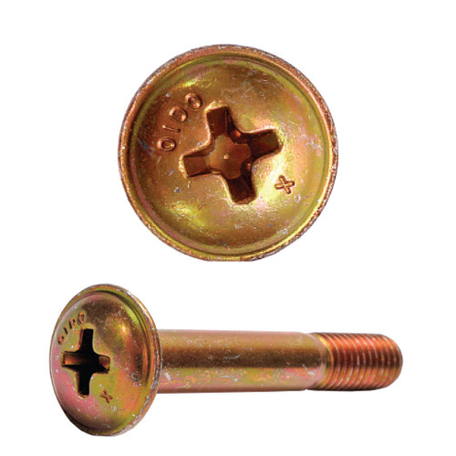
    Is it possible you could use something like these, Eric?

    MS16998 (NAS1351-3) & MS21042
    Attached Images Attached Images
    John Evens
    Arvada, CO
    Kitfox SS7 N27JE
    EAA Lifetime
    Chap. 43 honorary Lifetime

  10. #130
    Senior Member PapuaPilot's Avatar
    Join Date
    Nov 2013
    Location
    Nampa, Idaho
    Posts
    1,227

    Default Re: The Barn Find Build

    The AN525 pan-head screw is also a structural screw that could be used with the low profile nuts.

    You could also use clevis pins with a washer and cotter pins.

    Phil Nelson
    A&P-IA, Maintenance Instructor
    KF 5 Outback, Cont. IO-240
    Flying since 2016

Posting Permissions

  • You may not post new threads
  • You may not post replies
  • You may not post attachments
  • You may not edit your posts
  •